Power Distribution:
TIVA, solenoid and servo power was run off two 7.2V batteries in parallel. A 3A fuse was used to protect the TIVA from current surges, but this fuse was bypassed for pump and LED power. Electronic speed controllers (ESCs) were used instead of H-bridges. ESCs have their own current surge protection so fuses weren't needed to power them. TIVA and water pump/LED kill switches were implemented for testing purposes. Two buck converters and one upregulator converter were used to achieve desired voltages to power the TIVA, and achieve 5V for servo control. Jet pumps were run off of their own, separate 9.6V batteries.

TIVA Pinouts:
Three PWM outputs for servo/ESC control, 8 digital outputs to control LEDs/pumps/solenoids, XBEE tx, 1 digital input for XBEE RX, 1 analog input from fuel indicator PIC

Ship Lighting:
Two RGB LEDs controlled by MOSFETs to indicate home team, paired v unpaired, controlling team, and fuel status (on/off)

Fuel Level Sensing:
A 12F572 PIC was used to communicate with a provided pic that was mounted to the ship fuel tank in order to report the fuel status of the ship. RA0 reported an analog output to the TIVA that signified the changing fuel levels

Boat Thrust/Steering:
A servo was via push-bar to control the direction of thrust from the jet pump motors. ESCs are also controlled via servo style control (pulse-width of 1.5 ms is 0V, 2 ms is full power, 1.0 ms is full reverse)

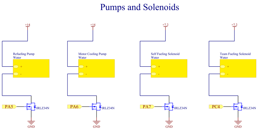
Ship Water Pumping/Distribution:
Two pumps were used inside the ship, one to cool the jet pump motors, and another to pump water out of the gun, or allow for self refueling. Two solenoids were used to control whether water flowed out of the gun or into the fuel tank. Pumps and solenoids were controlled via MOSFETS
Ship Communication:
An XBEE Pro was used to send information packets from the ship TIVA to the XBEE and vice-versa

